参考にはならないかもしれませんが…
2つのLEDの点灯/消灯をプッシュスイッチ操作でバイナリチックに切り替えていくスケッチです。
大まかにいうと
タイムカウンタを 2つ持っていて、PC のキーボードに類似したキーリピートの動作を実現しています。(複雑に見えますが、実際はそれほどでもありません)
…が。
もうだいぶ前の話なんで記憶が曖昧。後で再検討します m(_ _)m
/*
  Button2LED

 Turns on and off a light emitting diode(LED) connected to digital
 pin 13, when pressing a pushbutton attached to pin 2.
 And turns 2 LEDs when trigged a pushbutton (as binary status).


 The circuit:
 * LED attached from pin 9 to ground
 * LED attached from pin 10 to ground
 * LED attached from pin 13 to ground (for monitoring pushbutton)

 * pushbutton attached to pin 2 from +5V
 * 10K resistor attached to pin 2 from ground


 created 2005
 by DojoDave <http://www.0j0.org>
 modified 17 Jun 2009
 by Tom Igoe

 modified 2009/11/15
 by 熾火研究所(Okibi Labo.)


  http://www.arduino.cc/en/Tutorial/Button
 */


// constants won't change. They're used here to
// set pin numbers:
const int buttonPin = 2;     // the number of the pushbutton pin
const int ledPin00 =  9;     // the number of the LED pin
const int ledPin01 =  10;    // the number of the LED pin
const int ledPinIdc = 13;    // the number of the LED pin
// set voltage value for LED as
//         赤橙黄緑 => 1.8V / 5.0V * 255 = ca.90
//         青紫白UV => 3.2V / 5.0V * 255 = ca.160
const int analogV =  160;      //
// set interval time for delay (msec) to
const int basedelay0 = 700;
const int basedelay1 = 50;


// variables will change:
int buttonState0 = 0;     // variable for reading the pushbutton status
int buttonState1 = 0;     // variable for pushbutton status of 1-loop before
int LedState = 0;         // variable for keeping the LED status
long timeCount = 0;            // variable for keeping base timer
long btnRepeatCount0 = 0;      // variable for keeping timer
long btnRepeatCount1 = 0;      // variable for keeping timer


void setup() {
  // initialize the LED pin as an output:
  pinMode(ledPin00, OUTPUT);
  pinMode(ledPin01, OUTPUT);
  pinMode(ledPinIdc, OUTPUT);
  // initialize the pushbutton pin as an input:
  pinMode(buttonPin, INPUT);
  // initialize the time counter:
  timeCount = millis();      // variable for keeping base timer
  btnRepeatCount0 = millis();      // variable for keeping timer
  btnRepeatCount1 = millis();      // variable for keeping timer

  // open the Serial Port for debug output
  Serial.begin(9600);
}

void LedDrive() {
      // increment LED status:
      LedState += 1;
      LedState = LedState & 3;   // This statemant (line) isn't needed :-P
      // drive LEDs:
        if ((LedState & 1) == 1) {
          // turn on LED00:
          analogWrite(ledPin00, analogV);
        } else {
          // turn off LED00:
          analogWrite(ledPin00, 0);
        }
        if ((LedState & 2) == 2) {
          // turn on LED01:
          analogWrite(ledPin01, analogV);
        } else {
          // turn off LED01:
          analogWrite(ledPin01, 0);
        }
      // Clear the button counter 1:
      btnRepeatCount1 = millis();
}

void loop(){
  // get timer:
  timeCount = millis();
  // read the state of the pushbutton value:
  buttonState0 = digitalRead(buttonPin);

  // check if the pushbutton is not pressed:
  if (buttonState0 == LOW) {
    // Clear the button counter:
    btnRepeatCount0 = millis();
    btnRepeatCount1 = millis();
    // turn off Indicator LED:
    digitalWrite(ledPinIdc, LOW);
      // if the button JUST RELEASED:
      if (buttonState1 == HIGH) {
        // call LED Rrive Routine:
        LedDrive();
      }
  // if the pushbutton pressed:
  } else {
    // turn on Indicator LED:
    digitalWrite(ledPinIdc, HIGH);
      if ((timeCount - btnRepeatCount0  >= basedelay0) &&
          (timeCount - btnRepeatCount1  >= basedelay1)) {
        LedDrive();
      }
  }

  // stock pushbutton status:
  buttonState1 = buttonState0;


/* for debug --- value check ( to SerialPort ) */
  Serial.print("LedState:");
  Serial.print(LedState);
  Serial.print("  timer:");
  Serial.print(timeCount);
  Serial.print("  btnRep0:");
  Serial.print(btnRepeatCount0);
  Serial.print("  btnRep1:");
  Serial.println(btnRepeatCount1);

}
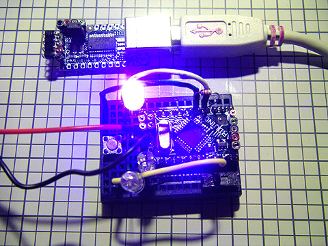
ソース中に記載してあるとおり、LED は 9番と10番(アナログ出力ポート)に接続します。また、オンボード LED のない mini や LilyPad などの場合、好みに応じて 13番ピンにも接続します。
スイッチは、プッシュオンタイプ(つまりもっとも普通な押しボタン)のスイッチを、5V と 2番ピンの間に繋ぎます。2番ピンは抵抗でプルダウン(2番→抵抗→GND)します。値は 10kΩ程度で。
LED の接続をアナログポートにした理由は、電圧調整のため。スケッチの中にコメントで計算式を載せてある。3.3V 駆動の Arduino の場合には値を変える必要がある。
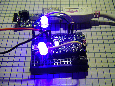
Arduino Mini で組んでドライブしている様子です。紫色(近紫外)LED を使用しているので色がへんです。見えにくいですが、 Arduino の左側にあるタクトスイッチを押すと(正確には押して離す、または押し続ける)と 2つの LED 状態が変わってゆきます。
また、スイッチよりも更に見えにくいですが、13番ピンに LEDが繋いであり、タクトスイッチ押下により点灯します。オンボードに LED がついている Duemilanove や Pro などでは、何もつながなくてもオンボード LED がスイッチ押下に連動して点灯/消灯します。
単純に、キーを押していたら作業をする、というスケッチだと、こんな感じ。
「ピポ」と鳴る。 鳴っている間、すぐにはキーを見張りにいかないので丁度よいディレイの役割をしてくれているが、もしキー押下時のタスクが一瞬で終了してしまうようなものだった場合、Delay を挿入するとよい。
/*

pipo

http://code.google.com/p/arduino-tone/
http://itp.nyu.edu/physcomp/Labs/ToneOutput

Arranged by OkibLabo 2009/12/05

 The circuit:
 * Speaker attached from pin 13 to ground (thru ~1K resistor as needs)
 * pushbutton attached to pin 2 from +5V
 * 10K resistor attached to pin 2 from ground

 */

#include <Tone.h>
Tone tone1;

int buttonState = 0;

const int pushBtn =   2;
const int pseudoGND = 3;
const int pseudoVCC = 4;
const int buzzer =   13;

void setup()
{
  tone1.begin(buzzer);
  pinMode(pushBtn, INPUT);
  pinMode(pseudoVCC, OUTPUT);
  pinMode(pseudoGND, OUTPUT);

  digitalWrite(pseudoVCC, HIGH);
  digitalWrite(pseudoGND, LOW);
}

void loop()
{
  buttonState = digitalRead(pushBtn);

  if(buttonState == HIGH) {
    pipo();
  }
}

void pipo()
{
    tone1.play(NOTE_B5);
      delay(100);
    tone1.play(NOTE_G5);
      delay(100);
    tone1.stop();
      delay(10);
}
このスケッチでは圧電スピーカーを 13番ピンと GND に繋ぎ(音量や耐圧によっては抵抗を挿入すること!)、押しボタンスイッチを 2番ピンと 5V ピンに繋いである。また 2番ピンは 10kΩの抵抗でプルダウン。

